GEOTHERMAL ENERGY INVESTMENT
MEMORANDUM
Geothermal energy investment and cost estimates.
23-06-2014
By Ceran International Energy GMBH
A General.
On request of investors for the Geothermal energy projects of Ceran International Energy GMBH (CIEG) this memorandum gives a rough overview of the costs involved with the development and operations of Geothermal electricity production for Istanbul and Izmir. Although development of Geothemal energy electricity is coupled with uncertainties it is tried to give a realistic overview of the costs involved.
The main uncertainties are related to geographical information about the temperatures of the earth layers and the depth of these and the other main uncertainties are the drilling capabilities to reach these layers.
The given figures are based on information from Verkis our Geo Thermal partner from Iceland. Verkis is partly known with the Turkish areas involved with the proposed geothermal project. And the data from Verkis is also related to similar project studies from other project reports.
As an approach for the development of a geothermal energy plant we apply the following workplan (see Verkis Geo methodology);
(1) Gathering Exisitng Data.
(a) Geology, Geophysics, Geochemistry, existing wells, legalisation etc
(2) Evaluation of Data
(3) Prefeasibility report
(4) Drilling of exploration wells
(5) Feasibility report
(6) Concept design
(7) Design and Construction
(8) Commissioning and training
For more precise and detail information it is required gather more data and evaluate the data.(phase 1, 2 and 3 )
B Preliminary results;
With the limited information available we estimate the following results;
In Turkey you can expect resource temperature 220°C – 250°C, suitable for flash condense steam plant, in the Menderes valley and Gedis area. According to information we have the resource temperature in the Izmir area is 130°C – 150°C. To utilize this for generation of electricity a binary ORC technology will be needed. The largest binary plant units on the market are 20 – 25 MW and total investment cost will be 4 – 6 million USD per MW depending on temperature, cost of drilling and well capacity.
A higher net capacity of a field will be achieved by the use of more turbine systems. In that case several set-up costs can be split and lower the investment costs per system.
We are not familiar with the Pendik Istanbul area.
O&M expenses are distinguished into variable and fixed costs.
The average fixed O&M costs are below $ 0.02/KWh
The variable costs are not treaded on a variable base.
The tariff to be applied are depending on several parameters which are out of the scope of this memorandum
At this stage we are not able to say anything about the capacity of the field
D Applicable technologies and their cost
D1 GEOTHERMAL DUAL FLASH (GT)
MECHANICAL EQUIPMENT AND SYSTEMS
The Geothermal (“GT”) Facility produces 50 MW net of electricity. The facility uses a dual-flash GT cycle, which includes one ST with the capability to generate 55 gross MW based on a high-temperature, high-salinity brine. The GT Facility consists of production wells, a Turbine Generating Facility (“TGF”), a Brine Processing Facility (“BPF”), injection wells, and a plant injection well. GT fluid in mixed phase (steam and brine) from the production wells is piped to the BPF where the fluid is flashed at successively lower pressures to produce two separate pressure levels of steam to be delivered to the TGF. Additionally, the BPF will produce a concentrated brine to be further processed to remove solids prior to being re-injected into the reservoir. The GT production wells deliver the GT brine to the BPF where it is initially flashed in a separator drum to produce HP steam. The remaining brine is subject to an additional pressure reduction stage, in closed pressure vessels called crystallizers, which are operated in a manner to prevent the rapid scaling of the vessel walls and internal parts by the precipitation of solids from the brine. The low-pressure crystallizer is supplied with a small quantity of seed flow, concentrated brine from the primary clarifier, to provide a nucleus to which the solids in the crystallizer brine can attach themselves and be carried out with the brine leaving the crystallizer. The separated brine from the crystallizer is sent through an atmospheric flash tank to reduce pressure, and then further processed via a primary and secondary clarifier system where the solids produced are formed into a solid cake after being passed through a filter press, treated with acid and neutralizing washes, and steam and hot-air dried to produce a silica rich filter cake Steam at the two pressure levels from the BPF is delivered to the TGF and directed through steam scrubbers (one for each pressure level), which are designed to produce 99.95 percent quality steam, by removing free liquids and a proportion of the entrained liquids within the steam. The scrubbed steam is delivered to the ST. The ST is a condensing ST equipped with dual HP and LP inlets. Steam from the ST is condensed in a two-pass shell and tube condenser constructed of stainless steel, with part of the condensate used for cooling tower make-up, and the remainder pumped to the re-injection wells. Condensate pumps direct condensate to the circulating water system, the purge system, or the condensate injection system. The non- condensable gases are evacuated by a non-condensable gas removal system and vent products delivered to an H2S abatement system. Cooling water for the ST condenser is supplied by an induced-draft cooling tower. Circulating water pumps direct water from the cooling tower to the ST condenser. Make-up water for the cycle is supplied from the condensate from the ST condenser. Additional make-up water may be needed during the summer months. The figure below presents a simplified process flow diagram for a GT power plant configuration.

ELECTRICAL AND CONTROL SYSTEMS
The GT Facility has one ST electric generator. The generator is a 50 Hz machine rated at approximately 70 MVA with an output voltage of 13.8 kV. The ST electric generator is connected to a high-voltage bus in the facility switchyard via a dedicated generator circuit breaker, GSU, high-voltage circuit breaker and a disconnect switch. The GSU increases the voltage from the electric generator from 13.8 kV to interconnected transmission system high voltage. The GT Facility is controlled using a DCS. The DCS provides centralized control of the facility by integrating the control systems provided with the BPF, ST and associated electric generator, and the control of BOP systems and equipment.
OFF-SITE REQUIREMENTS Since the GT Facility is fueled by a renewable, underground fuel source, an off-site fuel source, other than incidental plant heating, is not required. Water for all processes at the GT Facility is obtained from one of several available water sources; however, due to the geography of most geothermal power plants, water is sourced from on-site wells. Processed wastewater is generally re-injected, if wells are the source of water, though many GT facilities utilize ZLD. Further, the electrical interconnection from the GT Facility is accomplished by interconnecting via the plant switchyard into the utility high-voltage transmission system.
CAPITAL COST ESTIMATE
The base Cost Estimate for the GT Facility with a nominal capacity of 50 MW is $6,243/kW.

For this type of technology and power plant configuration, regional adjustments took into consideration the following: seismic design differences, local technical enhancements (e.g., additional noise remediation that is generally required in urban siting), remote location issues, labor wage and productivity differences, location adjustments, and the increase in overheads associated with these five adjustments
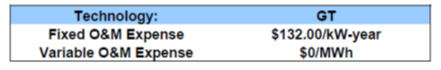
O&M ESTIMATE In addition to the general items discussed in the section of this memorandum entitled O&M Estimate, the GT Facility includes major maintenance on the ST, electric generator (each approximately every six years) and well field maintenance, which can vary depending on the GT resource. The table presents the FOM and VOM expenses for the GT Facility. In general, most GT facility operators do not treat O&M on a variable basis, and consequently, all O&M expenses are shown below on a fixed basis.
ENVIRONMENTAL COMPLIANCE INFORMATION Table below presents environmental emissions for the GT Facility.

D2. GEOTHERMAL BINARY (BINARY)
MECHANICAL EQUIPMENT AND SYSTEMS The Geothermal Binary (“Binary”) Facility produces 50 MW net of electricity. The Binary Facility consists primarily of three heat recovery power generation systems. These heat recovery power generation systems operate on a closed looped organic supercritical Rankine cycle using geothermal brine as a heat source, with a brine temperature of approximately 275°F. The geothermal brine heats the superheated organic working fluid within an evaporator. The cooled brine is then reinjected into the resource at approximately 140°F through injection wells. The heated supercritical working fluid is expanded through a multistage, radial inflow turbo-expander generator unit. The organic working fluid is cooled within a condenser before being pumped back to the supercritical pressure by a single pressure vertical turbine pump. Cycle heat rejection will be provided through three cooling towers. The design output (gross) of each turbo-expander is approximately 10,000 kW.
ELECTRICAL AND CONTROL SYSTEMS There are to be three turbine generators at the Binary Facility. Each turbine generator is to be an air cooled unit with static excitation designed for operation at 50 Hz, three-phase and 12.5 kV. Each turbine generator is to be rated for 18 MW with a power factor range of 0.85 lagging. The three turbine generators are to be connected to a single GSU connected through a generator circuit breaker and a switchgear main circuit breaker and underground cable to a switch on a common open air bus in the Binary Facility substation.
OFF-SITE REQUIREMENTS Since the Binary Facility is fueled by a renewable, underground fuel source, an off-site fuel source, other than incidental plant heating is not required. Water for all processes at the Binary Facility is obtained from one of several available water sources; however, due to the geography of most geothermal power plants, water is sourced from on-site wells. Processed wastewater is generally re-injected, if wells are the source of water, though many Binary facilities utilize ZLD. Further, the electrical interconnection from the Binary Facility is accomplished by interconnecting via the plant switchyard into the utility high-voltage transmission system.

17.4 CAPITAL COST ESTIMATE The base Cost Estimate for the Binary Facility with a nominal capacity of 50 MW is $4,362/kW.
For this type of technology and power plant configuration, regional adjustments took into consideration the following: seismic design differences, local technical enhancements (e.g., additional noise remediation that is generally required in urban siting), remote location issues, labor wage and productivity differences, location adjustments etc.
In general, most GT facility operators do not treat O&M on a variable basis, and consequently, all O&M expenses are shown below on a fixed basis
OUR PROJECTS
We handle a wide range of oilOIL RAFFINERIES
Our Department
APPOINTMENT
Get in touchRecent News
The latest news from Ceran International Energy


